
Sustainable Braking®
Wind Turbine Technology
The patented Ogab® Sustainable Braking system prevents critical failures due to fires, increased safety levels, and significantly reduces maintenance costs and operational downtime.
OGAB®
Sustainable
Braking®
Preventing critical operational failures due to fires caused by overheating brakes.
117 wind turbines catch fire each year because of the overheating of mechanical parts combined with flammable substances inside the body of the turbine being in close proximity. Ogab® offers a solution that provides a reduction in maintenance costs and downtime whilst improving safety and avoiding toxic emissions entering the atmosphere.


1.0 Introduction
All wind turbines are equipped with both aerodynamic and mechanical brakes. Under high wind velocities it might be necessary to activate the brake mechanism to avoid over-speed and subsequent catastrophic damage to the nacelle or the whole assembly. Wind turbine mechanical brakes are installed on the main shaft to slow down the blades and stop them in a reasonable amount of time in case of an emergency. In the wind turbine industry, the performance and efficiency of the brake systems are crucial for the safety of system. There have been several incidents reported of whole wind turbines catching fire leading to significant financial loss and, in some cases, catastrophic fatal losses.
Mechanical brake systems in majority of wind turbines consist of a disc brake which operates on an induced friction between rotating and stationary discs inside the brake. Disc brakes consist of two principal components- the rotor and stator. The rotating disc (rotor) is keyed to the main turbine shaft and rotates with the turbine blades while the stator (brake lining) is attached to the nacelle. When mechanical brakes are activated, brake linings squeeze the rotor and create friction which reduces the speed.
In other words, the primary function of brakes is to convert the kinetic energy of wind turbine blades into heat/thermal energy by creating friction. Due to the enormous weight of turbine blades (each blade can weight up to 12 tonnes) and the consequent moment of inertia and rotating kinetic energy releases a significant amount of heat into the wind turbine’s nacelle in case that the mechanical brake system is activated. Considering that there are many oil circuits within the nacelle for various purposes, releasing such amount of heat during the braking procedure can be very dangerous and ignition of fire can be a possible consequence of such procedure.
In this study, a novel technology is developed and deployed to reduce the brake disc temperature of wind turbine in the case that mechanical brakes are activated. By successful demonstration of such unique technology, it is possible to alleviate the safety concerns mentioned above and prevent any catastrophic incident while ensuring safe and smooth operation of the wind turbine.
2. Selected Wind Turbine for Test Case
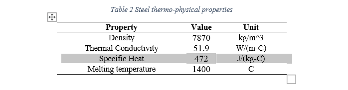
The selected wind turbine is 1.5 MW GE product with 3 blades where each blade is 35m in length and weight 12 tonnes. The brake system consists of a single disc and two brake pads (brake linings) which are attached to a stationary structure within the nacelle. Wind turbine brakes are often made of steel due to its desirable mechanical properties and the ability to tolerate harsh working environment.
2.1 Heat Generation Calculation
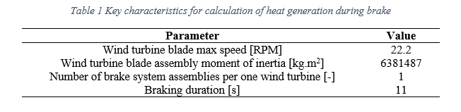
As mentioned in the introduction, the function of brake is to convert the kinetic energy to thermal energy or heat. Therefore, it is necessary to calculate the amount of heat that is released by the wind turbine blades during the brake. Table 1 outlines the key characteristics required for the calculation.
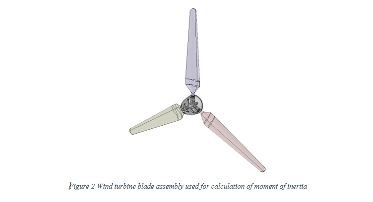
Since, the rotor blades are moving in a circular motion it was required to calculate the rotational kinetic energy. The moment of inertia was calculated for the complete wind turbine blade assembly that rotates together as shown in Figure 2 below.
Generated heat is calculated from the maximum rotational velocity of 22.2 RPM (2.32 rad/s) to a complete halt (0 RPM). The rotational kinetic energy of the wind turbine assembly is calculated via Equation 1.
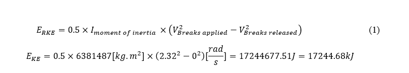
Considering that this amount of rotational kinetic energy is dissipated within 11 seconds (which is the braking period) then the heating power from all brake disc assemblies can be obtained as below:
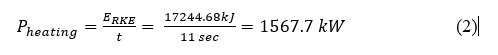
Then the heating power per brake disc assembly is achieved as following:

Therefore, such value was used as heating power that is dissipated by the brake’s disc and pads during the braking period
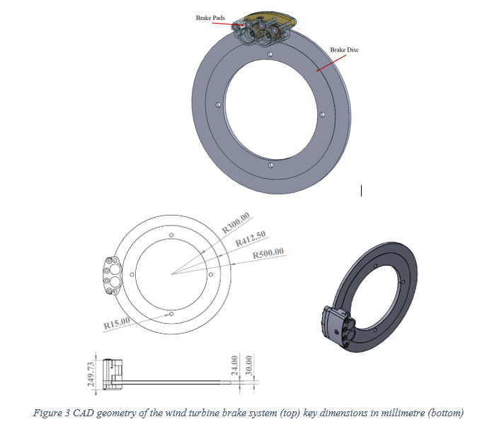
2.2 Brake System Geometry
The brake disc assembly consists of a single rotating disc and two brake pads that are clipped to the calliper as shown in Figure 3.
2.3 CFD Simulation Setup
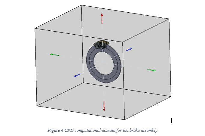
Due to the nature of the physics involved in this project, transient analysis was employed to accurately resolve the development of temperature gradients and accurately model the real physics of the phenomena. Total time of 300 seconds with time step of 0.05 second was used for this purpose. The computational domain shown in Figure 4 was adjusted to be adequately large to include all the relevant effects within the physics of the problem.
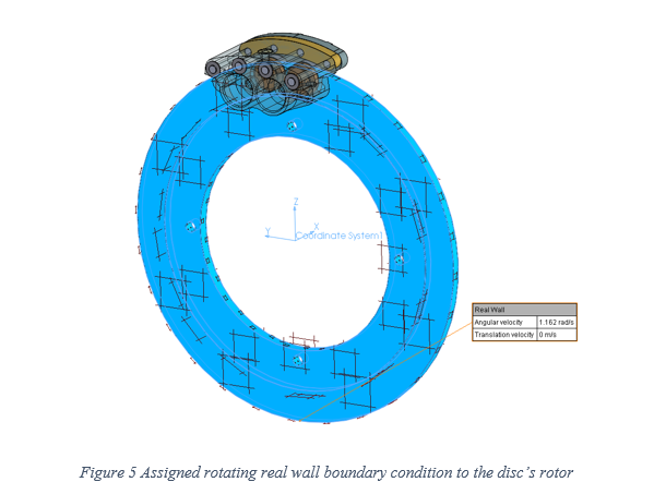
To account for the effect of disc rotation, a rotating real wall boundary condition was assigned to the disc (rotor) with the value of 1.162 rad/s which was obtained based on the disc diameter and wind turbine velocity. Such value was the average of top speed (22.2 RPM) and full stop speed (0 RPM). Figure 5 depicts the assigned boundary condition to all surfaces of the rotating disc (shown in blue colour).
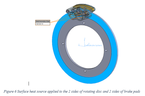
The calculated heating power of 1567.7kW obtained in section 2.2 was assigned to the 2 sides of the brake disc (as a surface heat source) and to the 2 sides of the brake pads (again as a surface heat source) which are in contact with the rotating disc (divided equally between 4 surfaces) as shown in Figure 6. This heating power was continuously active during the first 11 seconds (which is the duration of the braking) of the transient simulation.
To compare the effectiveness of proposed brake cooling technology, CFD simulations were performed for 2 general cases as “without cooling system” and “with cooling system”. Therefore, it was required to design a special nozzle for the case “with cooling system” that can be used for cooling.
3.0 CFD Simulation Results
For the case with proposed brake cooling technology, the system was activated onset of the braking function (brakes engaged), then it remains active for the braking period (i.e. for 11 seconds) and then it was remained operative for an additional 289 seconds (i.e. till t=300s) to achieve the effective cooling. During this 300 seconds of transient simulation, the brake linings and the rotating disc were in contact only for the first 11 seconds (i.e. from t=0s to t=11s) and all the heat that was generated as the result of friction was released during this time. At t=11s till t=300s the brakes were released, but the cooling system remained operative. The qualitative and quantitative results of the brake system without cooling and with cooling are presented in this section. The results are compared at two time moments as t=11s (which is the end of the braking period) and at t=300s (which is the end of the simulation).
Figures 16 and 17 depict the temperature of rotating disc at the end of the braking period (i.e. t=11s) and at the end of the transient simulation (i.e. t=300s) respectively.
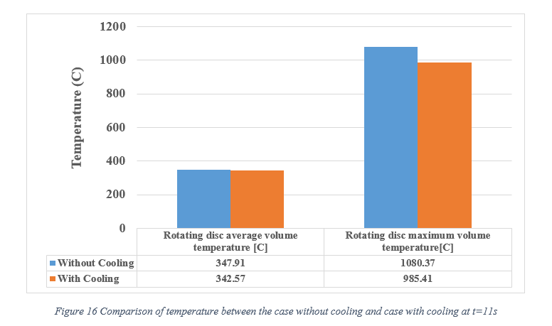
As evident from Figure 16, deploying the cooling technology proved to be effective as it reduces the rotating disc average volume temperature from 347.91C to 342.57C (1.53% improvement) while the maximum disc volume temperature reduces from 1080.37C to 985.41C (8.79% improvement) during the first 11 seconds of braking. The suggested cooling technology provided excellent results after 300 seconds as highlighted by the results in Figure 17. With such technology it was possible to reduce the brake disc average volume temperature from 307.65C to 192.65C (37.38% improvement) while the maximum disc volume temperature reduces from 438.84C to 345.63C (21.24% improvement).
Figures 18 and 19 present the evolution of disc average volume temperature and disc maximum volume temperature, respectively.
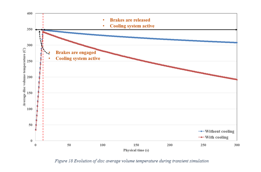
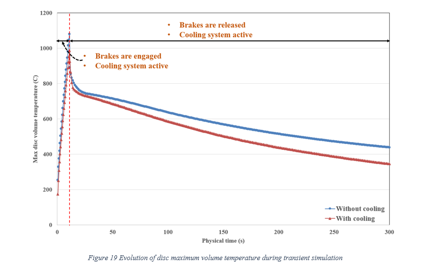
As clear from these figures, the proposed cooling method was very effective in preventing the disc average temperature from escalation. It can be seen that by deploying the cooling system the escalation rate of the temperature during the braking period is reduced, leading to lower temperature at t=11s. At the same time, such system assist the natural cooling of the brakes by increasing the reduction rate of temperature after the time that brakes are released (i.e. t=11s to t=300s).
Figure 20 demonstrates the temperature contour plots with integrated velocity vectors for both cases as without cooling and with cooling at the end of braking period (i.e. at t=11s). The velocity vectors exhibit that the disc rotation and cooling were properly set up during simulation.
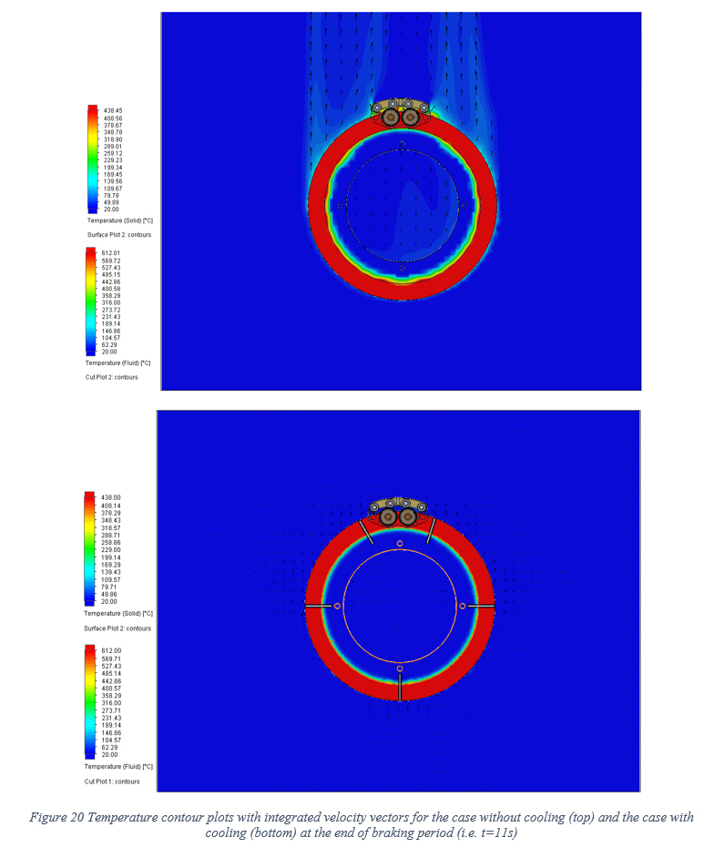
Figure 21 presents the temperature contour plots with integrated velocity vectors for both cases as without cooling and with cooling at the end of simulation (i.e. at t=300s). As evident, there is substantial improvement in terms of reducing the disc temperature by deploying the cooling technology. For the case without cooling majority of the disc temperature is in the range of 250C to 430C, while for the case with cooling majority of the disc temperature is in the range of 60C to 300C. This highlights that by allowing the cooling system to be operative only for a few minutes after braking, it is possible to remarkably reduce the rotating disc temperature.

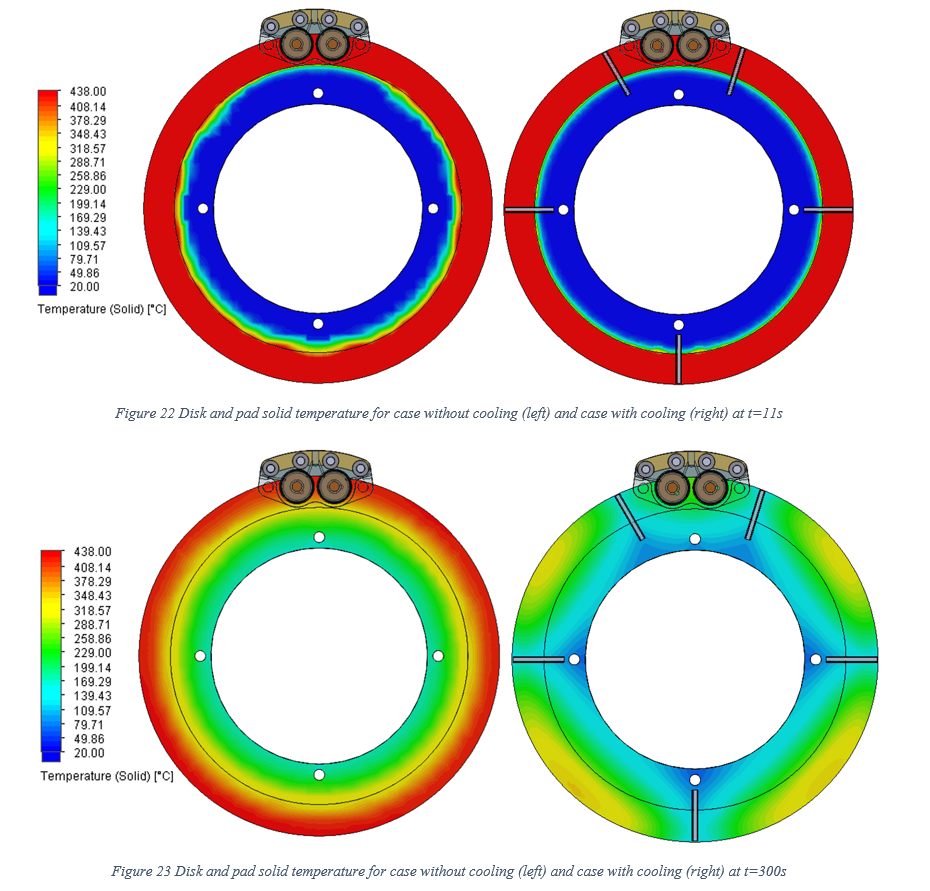
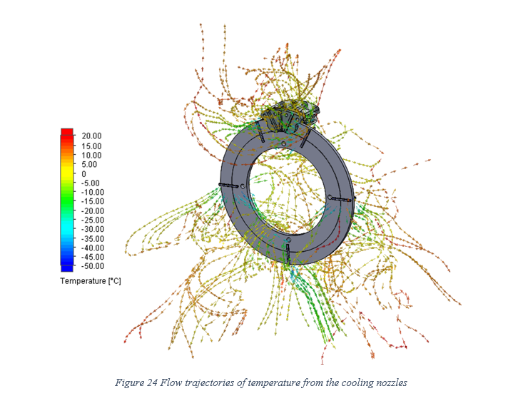
Figure 24 presents the flow trajectories of temperature from the cooling nozzles for the case with the cooling system. The nozzles were subtly located so that it can achieve the best performance for the cooling. We obtained such configuration as a result of careful investigation of earlier CFD runs and parametric study of key geometrical distances.
4.0 Conclusions
It was shown that the proposed cooling technology was very effective in reducing the rotating disc average temperature. It was demonstrated that with utilisation of such novel technique it is possible to reduce the disc average volume temperature by the maximum value of 1.53% after 11 seconds and by 37.38% after 300 seconds. Furthermore, the disc maximum volume temperature was reduced by 8.79% after 11 seconds and by 21.24% after 300 seconds.
The stated improvements in reduction of brake disc temperature were directly related to the air pump capacity and its mass flow rate. Depending on the interior design of the nacelle, larger capacity air pumps with higher mass flow rates can be deployed leading to lower brake disc temperature. On the other hand, with the proposed system it is feasible to alleviate the safety concerns regarding the fire incident inside the nacelle due to the high temperature issues as a consequence of emergency brake. Excessive heat from emergency mechanical braking is dampen by the proposed system and therefore, the whole system is more reliable. Besides, it is possible to remove the complex aerodynamic brake system which operates based on changing the blade’s pitch angle and instead rely only on the mechanical brake that is equipped with the proposed cooling system. This will increase the economic feasibility of the system and reduce the costs and will eventually help to increase the market penetration of the wind turbines.
It should be noted that the proposed cooling technology was deployed to an existing brake system design. Therefore, its performance was limited by the nature of the current brake systems configuration. Considering the proposed cooling technology (which was proved to be very effective) during the design process of new brake system assemblies can enhance the cooling performance even further and provide more integrated configuration of the brake system (i.e. embedded cooling within the brake system).
Get the full facts and insight on the brake disc product life cycle
Ogab® can help make a change for the better. Contact us today to find out more about our Sustainable Braking technology and how it can help you.